Product Introduction Video
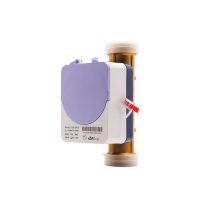
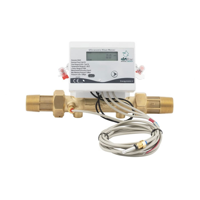
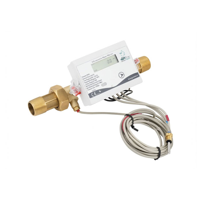
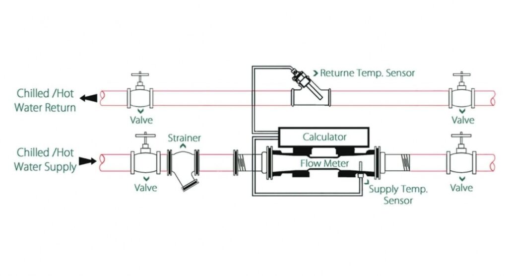
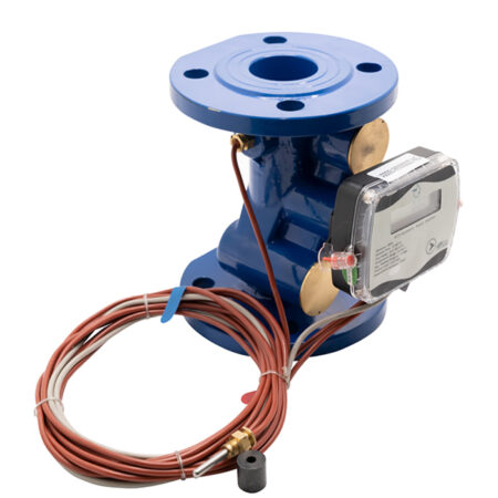
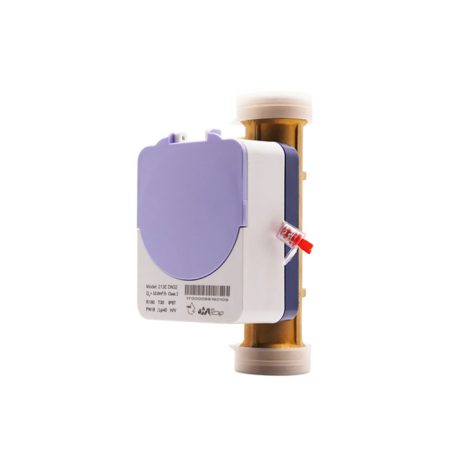
Main Components
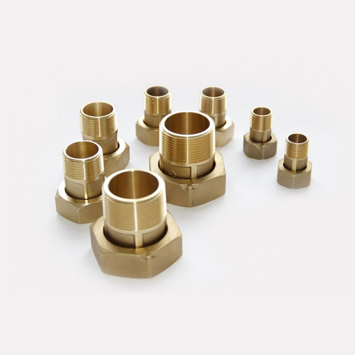
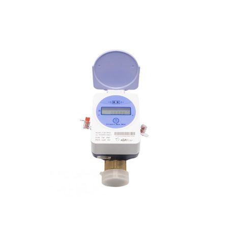
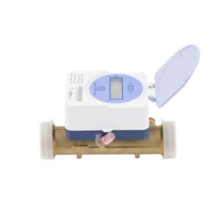
- Meter Body and Union Joints (Copper Joint)
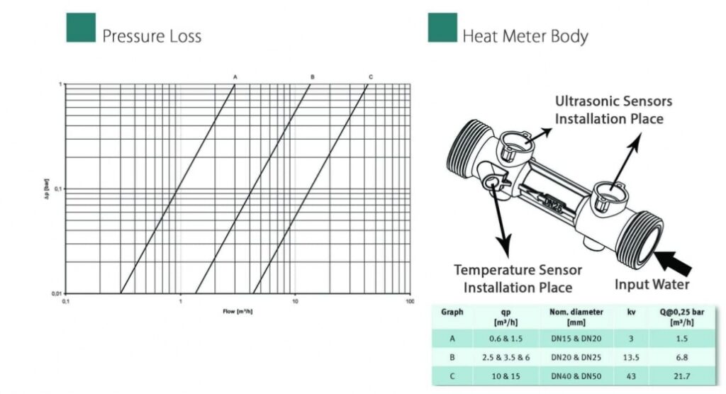
- 2 Ultrasonic Sensors
- 2 Temperature Sensors for Installation at the Inlet and Outlet of the Cycle
- Calculator and battery
Measurable Parameters
- Fluid Velocity (Water) and Instantaneous Flowrate (m³/hr)
- Total Flow Volume (m³)
- Fluid (Water) Flow Direction and Meter Operating Hours
- Consumed Heating and Cooling Energy (kWh)
- Cycle Inlet and Outlet Temperature (°C)
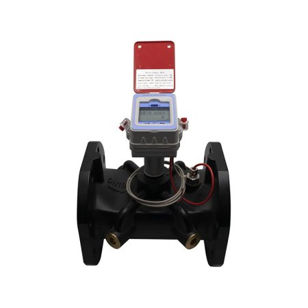
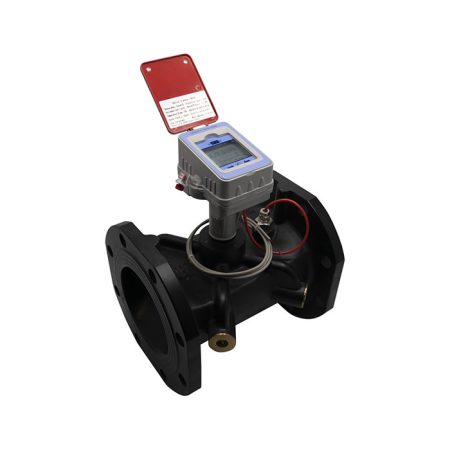
Size and Model Selection
Each heat meter has a minimum flow rate (Q min), nominal flow rate (Q nom), and maximum flow rate (Q max).
First, the cycle’s circulating flow rate must be calculated. Then, refer to the technical table and compare it with the flow rates of different sizes. The best selection is to match the cycle’s flow rate with the nominal flow rate (Q nom) of the meter.
| Net weight (kg) | Minimum height (mm) | Minimum with (mm) | Connection thread (inch) | The length of take over (mm) | Interface thread (inch) | The length of no take over (mm) | Maximum flow (m³/hr) | Nominal flow (m³/hr) | Minimum Flow (m³/hr) | Nominal Size (mm) | |
|---|---|---|---|---|---|---|---|---|---|---|---|
| 0.5 | 150 | 100 | R1/2 | 205 | G3/4B | 110 | 3 | 1.5 | 0.03 | 15 | DN15 |
| 0.7 | 150 | 100 | R3/4 | 235 | G1B | 130 | 5 | 2.5 | 0.05 | 20 | DN20 |
| 1.5 | 160 | 110 | R1 | 280 | G1 1/4B | 160 | 7 | 3.5 | 0.07 | 25 | DN25 |
| 1.8 | 180 | 130 | R1 1/4 | 305 | G1 1/2 | 180 | 12 | 6 | 0.12 | 32 | DN32 |
| 2.5 | 190 | 140 | R1 1/2 | 328 | G2B | 200 | 20 | 10 | 0.2 | 40 | DN40 |
Ultrasonic meters ranging from 1/2 inch to 1 1/2 inches are made of brass with threaded connections. The union adapter fittings are part of the meter and must be used during installation.
The preferred installation location for energy meters is at the cycle’s inlet unless installing the meter at the inlet is not feasible.

Reviews
There are no reviews yet.