
1) measuring equipment and tools (volume meter and water fluid flow meter)
To measure the amount of fluid flowing through a closed path (such as a pipeline) or an open path (such as a channel) with a certain cross-sectional area, various devices and equipment can be used. In some of these devices, the volume of the flowing fluid is read directly, and in others, after measuring the flow rate or the weight of the fluid, its volume is estimated with a good approximation.
According to the definition of OIML standard R 49-1: 2000, a water meter is a device that is used to continuously measure, maintain and show the volume of water passing through a route. According to this definition, the constituent parts of the contour can be divided into three main parts:
1- measuring section
2 – counter section
3- Display section
The measuring part of the contour is the part that is responsible for converting the volume, flow rate, speed, or weight of the passing water into quantifiable signs or signals. These signals are transferred mechanically or electronically to the counterpart and after counting and processing, the results are read from the display part.
2) Standards used for water fluid meters
OIML R49 standard and Iranian national standard under numbers INSO19191, ISO4064/I, and ISO 10385 and European Economic Community E.E.C.
3) Difference between volumetric meter and flow meter
Volumetric meter: it measures and displays the volume of the passing fluid regardless of the time parameter (units of measurement: liters, cubic meters, etc.)
Flow meter (flow meter): it measures the volume of fluid passing per unit of time (flow rate), and finally, flow meters can be used as volume meters because after calculating the flow rate, it is also possible to measure the total volume of the passing fluid. had (units of measurement: liter per minute, liter per hour, cubic meter per hour, etc.)
4) Some types of flow meters and meters in terms of measurement technology
Mechanical contours – Velocity contours (turbine) – Vertical turbine – (Single Jet) – (Multi Jet) – (Multi Jet) – Horizontal turbine of Voltman type – Volume contours – (Positive displacement) – (Oscillating Piston) Oscillating piston – (Reciprocating Piston) Back and forth – (Helix) Spiral – (Nutating Disk) Rotating disk – (Oval Wheel) Oval wheel – Inferential flowmeters – Pressure difference flowmeters – (Venturi) Venturi – (Nozzel) Nozzle – (Orifice) Orifice – (Target) Shield – (Point Tube) Pitot Tube – (Dall Tube) Slab Tube – (Variable Area) Variable Area Flowmeters – Special Flowmeters – (Ultrasonic) – (Electromagnetic) Electromagnetic – (Vortex Shedding) Vortex Shedding – (Thermal) Thermal – Quantitative Contours – (Coriolis) – (Hydraulic Wheatstone Bridge) – (Thermal Bridge)
5) Terms and definitions
Volumetric meter: a device suitable for a closed pipe, which includes chambers with a certain volume and a mechanism driven by the current, by which these chambers are filled and emptied sequentially with water. It estimates the flow capacity by counting the number of transient volumes through this device.
Speed meter: It is a device that is installed on a closed water channel and includes a moving part that is directly set in motion by the acceleration of the water flow. In other words, devices include a moving turbine that rotates around an axis perpendicular to the direction of water flow in the meter. The movement of this moving part is transferred by mechanical or other methods to an indicator that shows the volume of passing water.
Flow rate: outside the volume of water passing through the meter for the time it takes for this volume of water to pass
The flow starts Qs (Q start): It is the amount of flow that the meter starts to move at the pressure of three meters of water caused by a fixed head tank. In speed meters, this value depends on the amount of friction between the moving parts of the meter, and in volume meters, it depends on the water escape gap between the detection component and the working chamber.
Minimum flow rate Q1 (Qmin): the lowest flow rate at which the meter must show the volume of passing water within the maximum allowable error range (plus and minus 5%) or in other words, the minimum flow at which the meter performance curve enters the positive error range And it becomes negative 5%.
Transfer flow rate Q2 (Qt): It is the flow rate value in which the meter performance error is entered from the permissible range of positive and negative five to the permissible range of positive and negative two percent.
Nominal flow rate Q3 (Qn): It is the flow rate in which the flow meter must continue to work under normal conditions of use continuously and satisfactorily within the permitted range (positive and negative two) under the conditions of continuous and intermittent water flow.
Maximum flow rate Q4 (Qmax): is the maximum flow rate at which the water meter is required to operate satisfactorily for short periods of time without breaking down.
Flow range: The range limited by Q4 and Q1 is called the flow range, in which the flow range is divided into two upper and lower areas that are separated by Q2. In this range, the meter should not have an error greater than the maximum allowed.
Definition of nominal pressure (P): It is a numerical indicator of the working pressure of the meter, which is used in order to adapt it to other equipment connected to the meter and vice versa. The dimensions of all devices with the same nominal size (D) and marked with the same number (P) must be compatible with each other.
Maximum allowable working pressure (MAP): for a water meter, the maximum internal pressure that it can withstand permanently at a certain temperature. For cold meters, the maximum allowed working pressure will be the nominal pressure.
Nominal size (D): Numerical index of the diameter of the inlet and outlet of the meter, which is used to match it with other equipment connected to the meter and vice versa.
Pressure drop: the amount of drop in water pressure caused by the placement of the meter in a certain flow network.
Maximum allowable working temperature (MAT): the virtual maximum temperature that a water meter can withstand at its nominal pressure.
Pressure tolerance test: In the pressure tolerance test, each meter must stand without leaking or breaking at certain hydraulic pressures, usually 1.9 for the nominal pressure of the meter for 15 minutes or twice the nominal pressure of the meter for one minute without any leakage or bursting. to do
Determining the meter error curve in terms of flow rate: To draw the meter curve, it is necessary to perform an accuracy test at least in the following 4 flow rates.
Between Q2 and 1.1 × Q2
Between 0.45 × Q3 and 0.5 × Q3
Between 0.9 × Q3 and Q3
Between 0.9 × Q4 and Q4
Pressure drop test: This test is performed at different flow rates and at each flow rate, the amount of drop caused by the meter is measured and its curve is drawn. The pressure drop of mechanical meters in Q4 should not be more than one atmosphere.
Fatigue test: This test is performed by simulating harsh conditions and exposing the meter to ensure the resistance of the materials used. So that the deviation of the meter curve between Q1 and Q2 compared to before the test should not be more than 3% and between Q2 and Q4 more than 1.5%.
The characteristic number of the meter (N): the numerical value that represents the tabulated dimensional values of the meter and is indicated by the capital letter N.
IP68 standard: degree of protection or IP code is a term in the IEC60529 standard, according to which electrical equipment enclosures are divided by standard codes with two letters IP next to two digits, in terms of penetration against external factors. The first digit, which is between 0 and 6, specifies the level of protection against foreign hard objects and the protection of people. The second digit is between 0 and 8 and specifies the degree of protection against water penetration (and not any other liquid). The higher these numbers are, the higher the level of protection.
| Explanation of the first digit of the IP code according to IEC 60529 | |||
| first digit | Protection against foreign bodies | Defined protection for individuals | Force exerted on a foreign object |
| 6 | anti dust | a wire | 1 Newton |
| Explanation of the first digit of the IP code according to IEC 60529 | |||
| The second digit | Tested with | Protected against | details |
| 8 | The equipment is suitable for permanent immersion in water under the conditions mentioned by the manufacturer. This usually means that the device is sealed. However, in some equipment, it means that water can penetrate but not have a detrimental effect. | Immersion beyond 1 meter | Continuous immersion in water to the depth specified by the manufacturer |
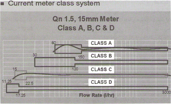
6) Division of meters based on work class
In ISO4064/I standards, meters are classified into four classes A, B, C, and D according to performance accuracy, in which class A has the lowest working accuracy. It should be noted that in the range of high currents, all meters work the same.
In addition, ISO 10385 standard is related to hot water meters, and in this standard, meters are placed in four classes A, B, C, and D in terms of working accuracy. The accuracy of each meter is determined by a standard test device by drawing a characteristic curve or an accuracy curve.
Class A meter (low accuracy): these meters have low accuracy in measuring hydraulic flow and their operating range is 60 to 150 liters per hour. This means that the said meter will show the correct reading with an acceptable error if it passes at least 60 liters and at most 150 liters of water per hour.
Class B meter (medium accuracy): these meters have medium accuracy in measuring hydraulic flow and their operating range is 30 to 120 liters per hour.
Class C meter (good accuracy): These meters have good accuracy in measuring hydraulic flow and their operating range is 15 to 22.5 liters per hour. Most home meters are of this type.
Class D meter (very good accuracy): This type of meter has very good accuracy in measuring the hydraulic flow and its operating range is 11.25 to 17.25 liters per hour.
| Counter class | Discharge | Qn<15m3/h | Qn>15m3/h |
| Class A | Qmin | 0.04 Qn | 0.08 Qn |
| Qt | 0.1 Qn | 0.3 Qn | |
| Class B | Qmin | 0.02 Qn | 0.03 Qn |
| Qt | 0.08 Qn | 0.2 Qn | |
| Class C | Qmin | 0.01 Qn | 0.006 Qn |
| Qt | 0.015 Qn | 0.015 Qn | |
| Class D | Qmin | 0. 0075 Qn | |
| Qt | 0.0115 Qn |
| Counter class | Discharge | Qn<15m3/h | Qn>15m3/h |
| Class A | Qmin | 0.04 Qn | 0.08 Qn |
| Qt | 0.1 Qn | 0.2 Qn | |
| Class B | Qmin | 0.02 Qn | 0.04 Qn |
| Qt | 0.08 Qn | 0.15 Qn | |
| Class C | Qmin | 0.01 Qn | 0.02 Qn |
| Qt | 0.06 Qn | 0.01 Qn | |
| Class D | Qmin | 0. 01 Qn | |
| Qt | 0.015 Qn |
7) Mechanical contours
One of the most common types of contours for direct measurement of the volume of water consumed and the main product of the major contour companies in the world is mechanical contours. In these contours, a flow detection component such as a propeller or a movable piston is used, the amount of movement and displacement of which is proportional and affected by the movement of the fluid, and by transferring the movement from this part and through the central axis to the counter, the amount of passing water volume is measured and will be recorded. It is possible to transfer the movement of the propeller or piston to the counter both in the form of a gear wheel (gear type) and in a combination of two permanent magnets and a number of gears (magnetic type).
The advantage of magnetic contours compared to gearbox contours is reducing the amount of contact of internal parts with water, precipitation of salts in it, and as a result, preventing the damage of the contour due to internal parts getting stuck. However, cases such as the effect of external magnetic fields on the performance of the contour, the phenomenon of disconnection in permanent magnets, or the absorption of possible metal shavings in water, are some of the disadvantages of this type of contour. Many reputable contouring companies have solved the above-mentioned problems in their products with the basic design and installation of anti-magnetic rings and the use of suitable and accurate permanent magnets.
Note: Magnetic meter and electromagnetic meter are different
Speed type mechanical counters
In speed contours, the flow-detecting component is a turbine or propeller that is placed in the water path and rotates freely due to the force caused by the movement of water. Due to the movement of the propeller, the volume of water passing through the contour is measured. The design of the propeller and the related chamber is such that a direct proportion is established between the rotation of the propeller and the speed of the fluid flow. In these contours, if the axis of the turbine is along the direction of the fluid flow, the contour is called a horizontal turbine, and if the said axis is perpendicular to the direction of the fluid flow, the contour is called a vertical turbine. Horizontal turbine contours are usually used in high sizes (volume) and vertical turbine types in low sizes (domestic contours).
If the water hits the propeller from several openings, it is called a multi-jet contour, and if it hits the propeller from one direction, it is called a single jet. Single-jet contours start to work at lower water speeds than multi-jet contours. In case, multi-jet contours show more resistance to dynamic shocks.
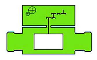
In mechanical type contours, if all the internal parts are in contact with water, they are called semi-dry type and if only the impeller is in contact with water (such as magnetic contours), if the rest of the parts are in contact with water except for the counterpart, they are called dry type.
– Number meters in the water
– Underwater gearbox set
Advantages:
– Cheap technology
– It is difficult to manipulate the dialer
– They are very accurate for the price
Disadvantages:
– It is difficult to read the dial (blurring)
– Sensitive to small particles in water
– The possibility of condensation under the glass
– Low lifespan
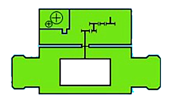
– dry gauge or filled with a special liquid
– Gearbox set in contact with water
Advantages:
– No steaming and transparency of the dial
(in the number gauge type with special liquid)
Disadvantages:
– Sensitive to small particles in water
(less than wet meters)
– Failure to adjust the dial direction
– Possibility of fraud and manipulation
– The possibility of steaming (in the type of dry gauge)
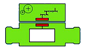
– No contact of water with the gauge
– No contact of water with the gearbox assembly
Advantages:
– The dial can be rotated in any direction
– Creating the possibility of remote reading
– Insensitivity to fine particles in water
– Invulnerability to network air shock
Disadvantages:
– Possibility of steaming due to lack of sealing
– Failure of the magnet to work correctly at high speeds (depreciation, chip absorption, external magnetism)
– There is more possibility of fraud and manipulation
– More complex manufacturing technology
Comparison of types of mechanical meters
Piston meter: suitable for high-quality water with high sand and particle content, high accuracy and high R, strong resistance to freezing and sub-zero cold, low starting flow rate, suitable for southern cities if the water quality is high, especially in cities due to Lack of water Most people have a source of water storage. Low resistance to high EC waters and sand and gravel, high accuracy class.
Dry multi-jet meter: suitable for any climate and any type of water, if it is not produced by a reliable brand, it may suffer premature failure due to the quality of the magnet. Weakness of measuring accuracy in low and high flow rates, medium accuracy class, resistance to salt water and very high EC, resistance to water hydraulic shocks, it is easier to manipulate the meter and remove unauthorized.
Semi-dry multi-jet meter: suitable for medium to high-quality water, high accuracy class, resistant to water hydraulic shocks, suitable for most regions of the country.
Single jet meter: low starting flow rate and more suitable than multi-jet, high accuracy class, lack of adequate resistance against water hydraulic shocks, suitable for apartment units, very reasonable price
8) ULTRASONIC FLOW METER
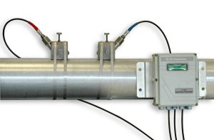
Ultrasonic flowmeters are in two types of function, Doppler and Transit Time, and in terms of installation, in two types: clamp on or in line.
The principles of operation of the ultrasonic flowmeter of the time difference (TRANSIT TIME)
One of the methods of measuring the amount of fluid flow is based on the time difference using ultrasonic waves, the basis of this method goes back to the Nobel Prize-winning physicist Lord Raleigh, who wrote in his book in 1877 on the theory of sound. (sound) published, described the propagation of sound waves in gases and solids, the method of measurement in this method is as follows:
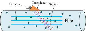
Inside an ultrasonic flowmeter, one or more pairs of ultrasonic sensors are installed on the cross-section of the pipe, each sensor can send and receive the ultrasonic signal, as a result, both ultrasonic sensors emit sound waves toward the condenser and receive the ultrasonic wave of the opposite sensor. the time of sending and receiving these signals is measured simultaneously (ultrasonic signals are produced by the electric voltage given to the piezoelectric crystals), and the time difference between sending and receiving the signal in the direction of the current and against the direction of the indicator The speed of the fluid is inside the tube, so if the time difference is zero (the speed of sending and receiving is equal), it means that the fluid is still and there is no flow.
As soon as the fluid flow or fluid movement is established, the speed of the ultrasonic signals increases in the direction of the fluid flow and decreases in the opposite direction of the flow, as a result, the passage time of the ultrasonic signals will be different in the direction of the flow and against the direction of the flow (less in the direction of the flow and in the opposite direction of the flow). more opposite direction) so the transit time difference measured by the sensors is directly proportional to the flow rate in the pipe.
By knowing the cross-sectional area of the pipe, the actual flow volume is calculated, the higher the flow speed, the greater the time difference between the ultrasonic signals in the direction and opposite direction of the flow, so the measurement will be simpler and more accurate (as long as the water flow is not confused) )
In order to measure the flow by ultrasonic method, it is not necessary to place the sensors inside the pipe wall, for example, with a clamp-on system, the sensors are closed directly on the outer surface of the pipe. These sensors can be installed at any time without interrupting the work. In belt systems, ultrasonic signals pass directly through the pipe wall and into the fluid flow. The signal moves inside the pipe and is reflected by hitting the opposite wall and is received and measured by another sensor.
In this case, the design of the belt system is unique, because by installing two sensors in front of each other, it is possible to measure the flow in very large pipes up to 4 meters in diameter, this increases the field of application of this system, flexibility Installation, process safety and high-cost efficiency are just some of the unique advantages of ultrasonic flow measurement systems.
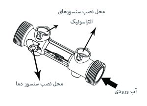
In the inline model, a piece called a reflector is used to increase the accuracy, in the non-reflector models, the second sensor receives the sound waves through the reflection of the impact of the sound waves on the wall of the flow meter.